Initial Sizing
Design Changes
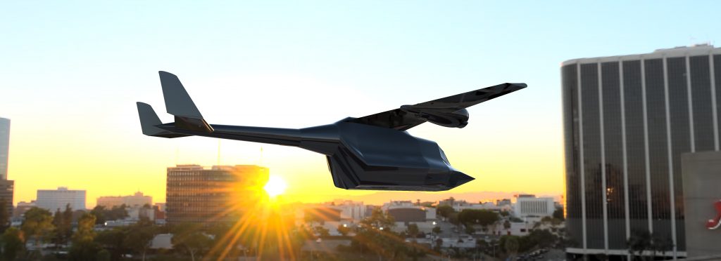
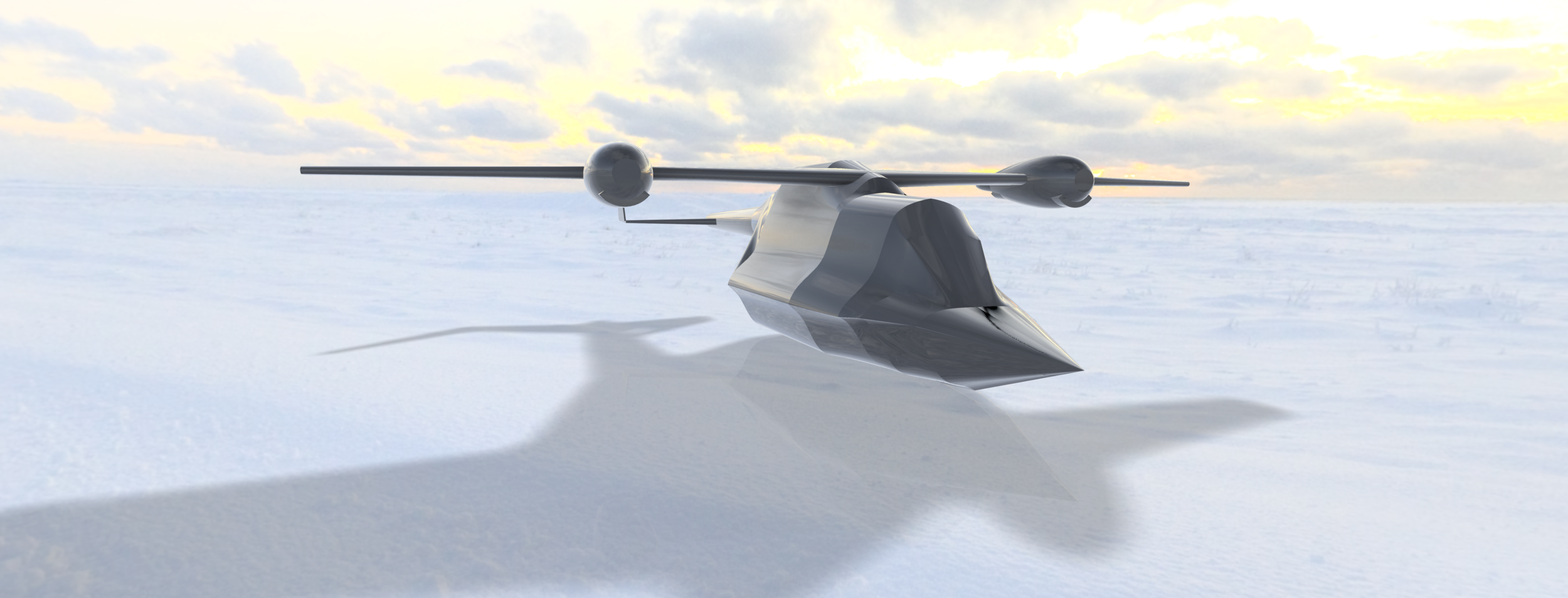
The original concept design of "Niska" included a curvy wing design with a winglet. However, upon weighing the pros and cons of including such a design in the concept, it was decided that the design should be revised to only utilize a conventional design. While winglets are proven to increase aircraft flight efficiency, they also added weight to the structure due to the weight of the winglets themselves as well as the wing reinforcements required to support the winglets [1]. It was decided to not include the winglets since the aircraft travels at a relatively slow speed and short distance. Simply said, the increased weight and complication on the tilting wing do not justify the use of winglets for relatively slow and short flights. Similarly, the empennage of the aircraft was also simplified to a more conventional H tail design rather than the original blended and curved design.
Figure 1, Comparison between the original design copied to Fusion 360 compared to the new design,
Render of The Aircraft
Wetted Area of Concept
The wetted area represents the amount of surface area of the aircraft directly in contact with air. This value is important as it relates the overall aerodynamic drag of the aircraft with the shape of the aircraft. The wetted area calculation was done utilizing Fusion 360 and the concept sketch produced before. Using Fusion, the concept sketch was traced and scaled into a digital drawing as seen in Figure 1 earlier. Fusion 360 was used in this rough work section as it was a program that I am experienced and comfortable with. my comfortability with the program allowed me to create estimations in a timely manner. Once the digital; drawings were drawn, further details were added in such as sectional cross areas of the fuselage and the general wing shape. These cross-sectional drawings help in producing the outline of the fuselage shape as seen in Figure 2. Using the "Loft" tool in Fusion, we were able to produce a 3D model of the fuselage. Once the model was produced, the model properties can then be analyzed using the built-in Fusion tool.
Figure 5, Wingspan of the aircraft
Hand Calculation Comparison
As proof of the accuracy, the horizontal stabilizer projected area was calculated manually from the hand-drawn sketch and compared to the fusion result. As seen in Figure 3, the sketch area of the horizontal stabilizer was found to be 17.50662 ft2. This value is 9% higher than the value calculated through fusion which was measured to be 16.037 as seen in Figure 4. The fact that the error is under 10% makes the CAD value to be acceptable and it can even be considered to be more accurate than the had calculation from the sketch as the sketch calculation could only be as accurate as the measurement tool used to measure the geometry of the shape. In this case, a ruler with a minimum increment of 1mm was used to measure the geometries of the horizontal stabilizer projected area. Utilizing fusion, the wetted area was calculated to be 1305.559 ft2. Similarly, fusion also allowed point-to-point measurement as seen in Figure 5, and the wingspan was measured to be 47.8 ft (14.67m) which allows the aircraft to Alan well in a 20m x 20m landing area.
Figure 2, Skeleton drawing of the aircraft and the 3D model of the aircraft.
Figure 3, Measurement of the horizontal stabilizer from Fusion 360.
|
Figure 4, The hand measurements of the horizontal stabilizer projected area. |
Figure 5, Wingspan of the aircraft |
|---|
L/D and Aspect Ratio
Utilizing the wetted area value of 1305.559 ft2 and wingspan of 47.8 ft found earlier, it was then possible to calculate the L/D using Equation 1 below [2].
Where Awetted is the wetted aspect ratio and KLD was assumed to be 10. The value of 10 was picked since Reymer had specified a value of 9 for propeller aircraft with non-retractable gear and 11 for propeller aircraft with retractable gear [2]. The value of 10 was chosen as it is estimated that the flying boat design with partially retractable gear would be more aerodynamic than an aircraft that has non-retractable gear but be worse compared to retractable prop aircraft due to the hull design which is optimized for motion on water [3].
The wetted aspect ratio was calculated to be 1.338308 using Equation 2 below.
Furthermore, the wing's aspect ratio was also calculated using Equation 3 with the known wingspan and wing projected area of 227.22 ft2 measured from Fusion 360.
The aspect ratio was found to be 7.689 which seems to be reasonable for the speed at which the aircraft is traveling and the purpose of the aircraft.
Summary
Figure 6, Table of results
The wetted area was calculated to be 1305.559 ft2 which resulted in an L/D value of 11.568. Due to the method of calculation, this value can be rendered to be mostly accurate especially considering some of the design changes that were applied to the design. The accuracy is proven to be within 10% of the hand calculations and removes the possibility of rounding errors and scale conversion errors that can be produced by manually calculating the separate areas.
References
[1] M. Verrastro and I. Dimino, “Chapter 21 - Morphing Devices: Safety, Reliability, and Certification Prospects,” in Morphing Wing Technologies, A. Concilio, I. Dimino, L. Lecce, and R. Pecora, Eds. Butterworth-Heinemann, 2018, pp. 647–682.
[2] D. Raymer, Aircraft Design: A Conceptual Approach, Sixth Edition. Washington, DC: American Institute of Aeronautics and Astronautics, Inc., 2018, Chapter 3.
[3] S. Gudmundsson, “Chapter 4 - Aircraft Conceptual Layout,” in General Aviation Aircraft Design, S. Gudmundsson, Ed. Boston: Butterworth-Heinemann, 2014, pp. 77–95.


